
Complete APRS Setup Guide for VR-N76 Transceiver: Protocol Initialization and Deployment Blueprint
The VERO VGC VR-N76 integrates a native hardware-based Terminal Node Controller (TNC) and embedded GPS modules to facilitate robust data packet reporting. Operating over standard AX.25 link-layer protocol frames, the Automatic Packet Reporting System (APRS) allows operators to exchange geographical data, text alerts, and tactical positioning information directly across local airwaves. This comprehensive manual details the baseline installation protocol required to initialize and optimize your hardware node.
Deploying App-Defined Radio Architecture
The VR-N76 series features an open digital data layer designed for seamless integration with mobile GPS and real-time mapping environments.
1. GPS Acquisition: Satellite Time Sync Protocol
Before an APRS node can broadcast reliable location telemetry, the internal digital tracking engine must achieve a 3D satellite fix. An inaccurate coordinate set risks flooding terrestrial iGates with corrupt network data.
- Antenna Orientation: Place the transceiver chassis in a clear, open outdoor sector. The integrated patch antenna requires a direct line-of-sight to the sky for initial ephemeris download (cold start).
- Temporal Validation: Monitor the top system status bar on the VR-N76 interface. Successful telemetry acquisition is confirmed when the local atomic date and time update automatically.
2. Configuring Core APRS Menu Parameters
With the tracking engine online, the radio identity parameters must be matched against standard amateur radio specifications inside the machine memory.
- Access the central system Menu and enter the APRS Settings panel.
- Callsign Validation: Input your regulatory callsign combined with the correct Secondary Station Identifier (e.g., K6ABC-7 for handheld units, K6ABC-9 for primary mobile vehicles).
-
Network Path Selection: Define the digital hop ceiling. Standard local network paths like
WIDE1-1, WIDE2-1are highly recommended to ensure adequate regional reach without generating redundant packet loops. -
Authentication Passcode: Input your specific numerical APRS verification token.
Technical Note: Valid tokens are computed based on callsign checksum algorithms and can be generated using standard web utilities.
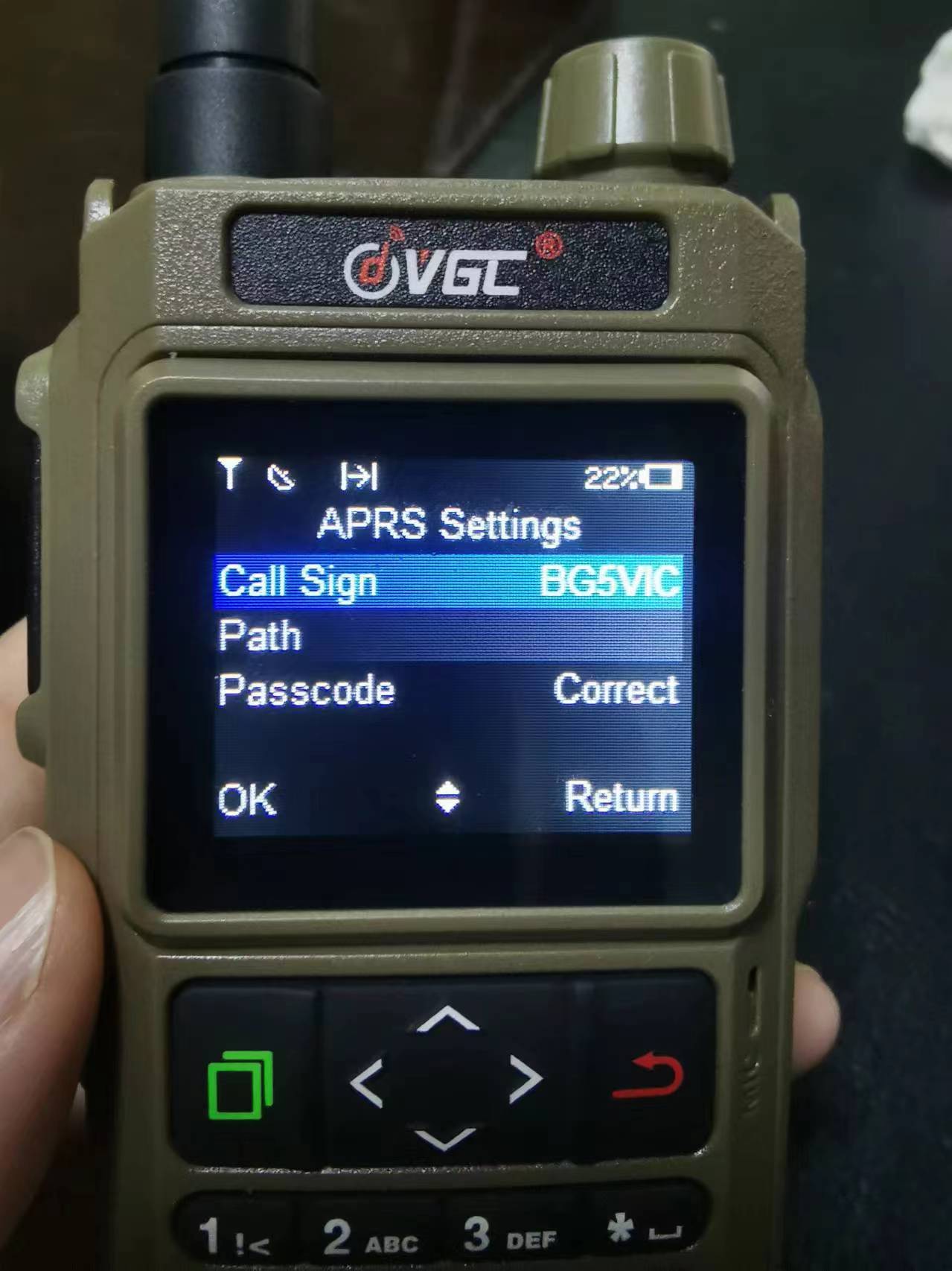
Figure 1: Entering specific station identification parameters into the hardware core.
Memory Allocation: Execute the save command before exiting to permanently flash the values to the EEPROM partition.
3. Activating Data Transport & Kinetic Tracking Rates
Once identity vectors are saved, the automated transmission scheduler must be balanced against the physical movement of your team.
- Navigate directly to the Digital Mode configuration panel.
- Protocol Toggle: Switch the main APRS tracking framework to ON.
- Interval Balancing: Select a transmission period that matches your current movement. High-speed overland transit requires tighter tracking intervals (e.g., 3–5 minutes), while stationary base camps should extend periods to reduce channel load.
- Channel Assignment: Lock the data execution loop onto your designated local APRS frequency channel (e.g., 144.390 MHz / 144.800 MHz).
- Modulation Frame: Confirm the digital interface logic is set strictly to APRS mode.
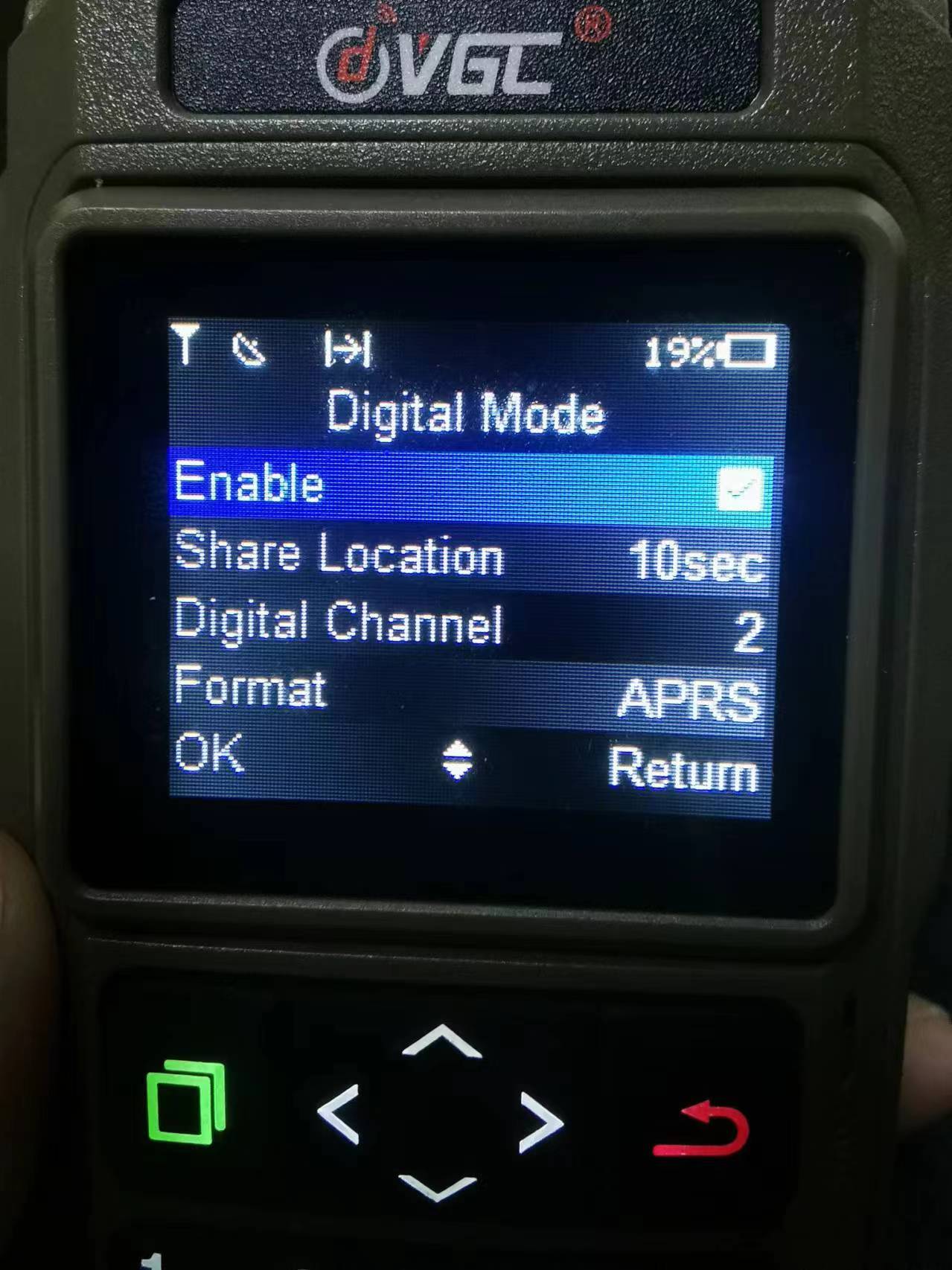
Figure 2: Customizing automated position reporting channels and telemetry intervals.
4. Passive Monitoring: Receive-Only Deployment
For localized search operations where maintaining silent RF profiles is mandatory, the system can be configured as a passive listening node:
- Maintain the primary Protocol Switch in the active (ON) status to decrypt surrounding AX.25 UI-frames.
- Adjust the Automatic Position Sharing Interval to OFF/Disabled to block the transmitter from firing automated location bursts.
5. Technical Troubleshooting & Configuration Conflicts
Symptom: EEPROM settings constantly revert to factory defaults?
Resolution: Verify data synchronization variables within your connected HT APP. If app-override is active, mobile sync cycles can overwrite manual radio modifications. Set local sync rules to maintain independent hardware authority.
Symptom: GPS status indicator visible but position lock fails?
Resolution: The internal patch array requires an unobstructed sky view. Metal overlanding roof racks or enclosed cabin cages degrade satellite signal reception; utilize dedicated external antenna links for high-density vehicle integrations.
Advanced APRS Network Engineering Resources:
Technical Documentation Center
Access official engineering schematics, firmwares, and standardized compliance updates for the VGC N-Series ecosystem.